
Post by david on Oct 15, 2007 23:50:50 GMT 1
In response to a request from Greg, here are some pictures of the deck camber I’ve built into my Bismarck. I’d already finished my deck before realising that Amati appeared to have no plans to incorporate this feature, so modifying the deck support beams to achieve this, (probably the best way), was out of the question. Studying the Brower plans, the rise of the deck is between 2.5mm – 3mm at the high point, enough to be noticeable at 1:200. An early idea was to cut card contours, map-like, and building them up with PVA to provide a base for the final deck, but I ditched it when I realised that because PVA shrinks when it dries I might end up with…the ends up!
Another concern was whether the photo-etched parts would fit a curved deck. Taking the aircraft hangar on the upper deck (which is also cambered), on one of the first transverse PE parts to be issued, as shown on the German site, Amati have made the footings below the 2 doors deep enough for it to be accurately seated on the cambered deck. In other words, the bottom of inner sides of the doors sits closer to the deck than do the outer sides. The plan I devised therefore was to position the superstructures and draw around them an outline onto the deck, and then to remove wood from the high point of the camber sufficient to seat these items. OK, all this means a lot more work, but I guess none of us embarked upon the building this leviathan in the first place to save time!
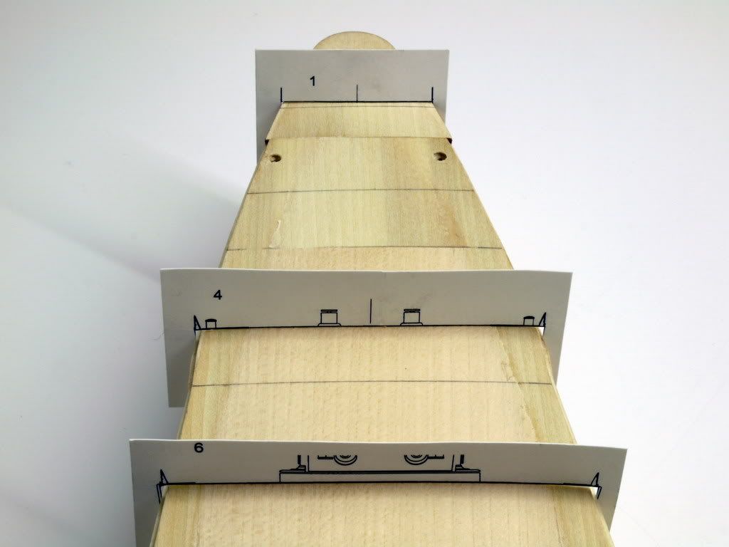
So, satisfied that a camber wouldn’t prevent an accurate build, I decided that I’d need to build up the deck using plan 'J', laying down sheets of lime wood. This was the option I had been trying to avoid because it would be laborious and not a little risky, but in the end I couldn’t think of a better way. Firstly, I scanned the Brower book to 1:200 and made a complete set of cross-sections.
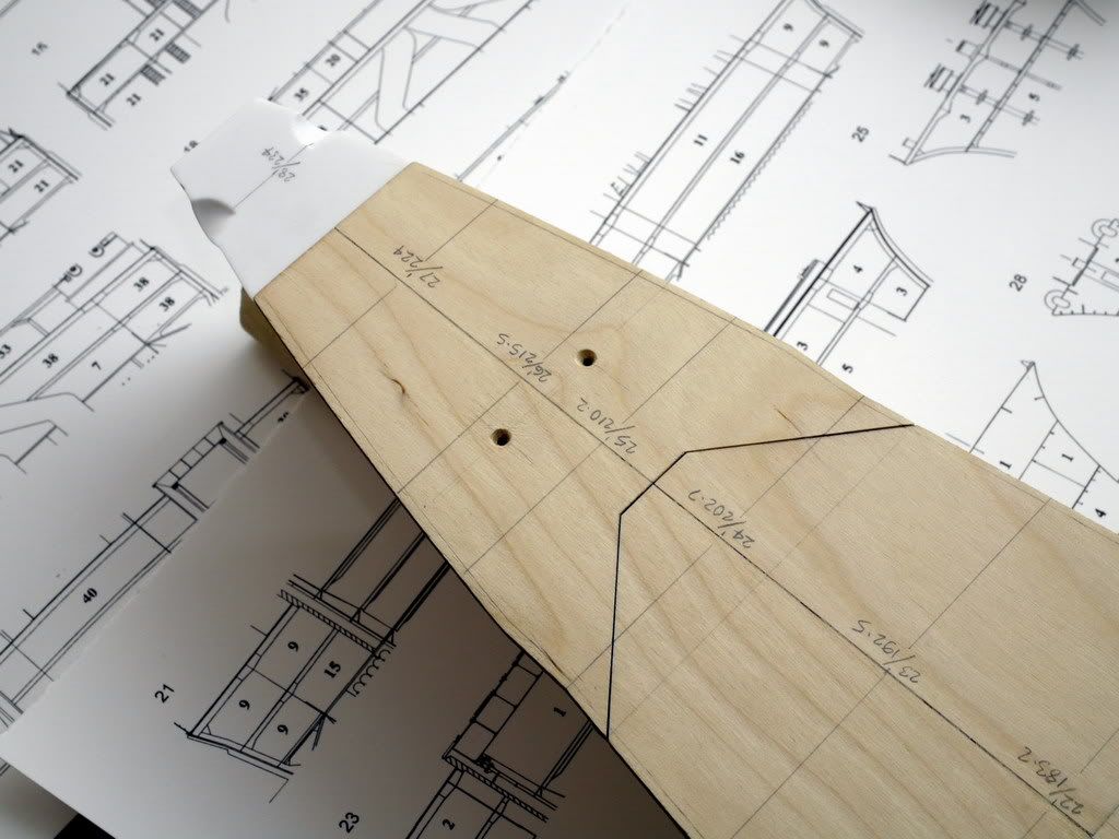
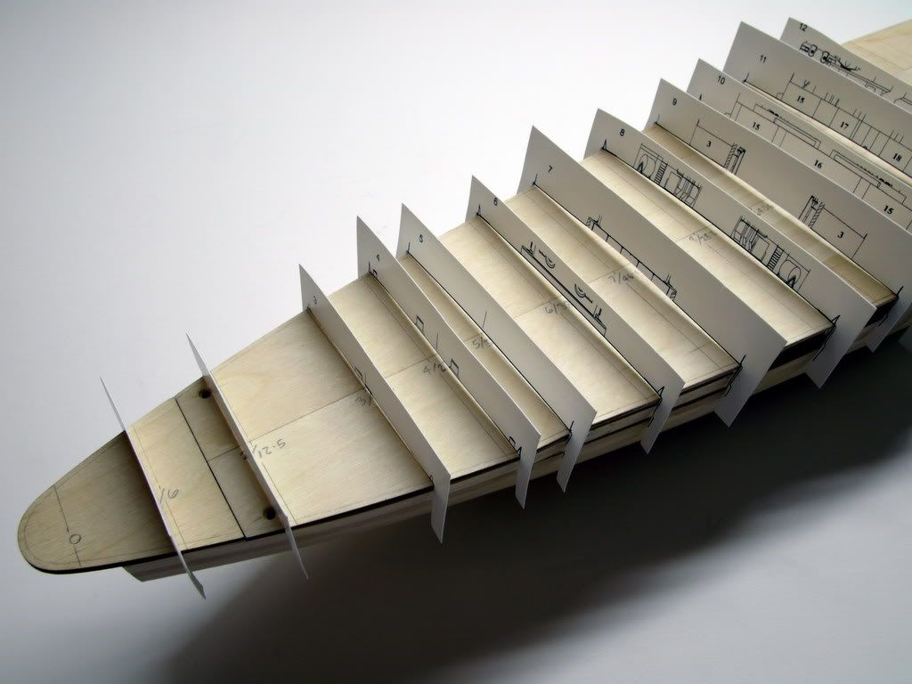
These were then cut out and positioned on the deck to establish the rough outline of the 1, 2 and 3mm contours. I first glued down a sheet of 1mm lime over the entire deck.
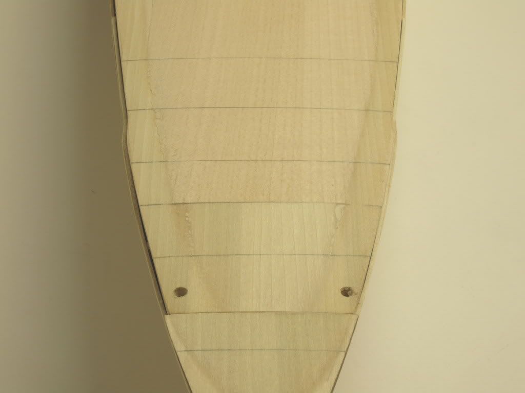
Only when it was too late did I think of marking the edge of the Amatie deck with a dark felt pen to help later when sanding down to the correct level. A second sheet of 2mm lime was then glued to the first layer, and as with the other, left to dry overnight with the deck screwed and weighted down.
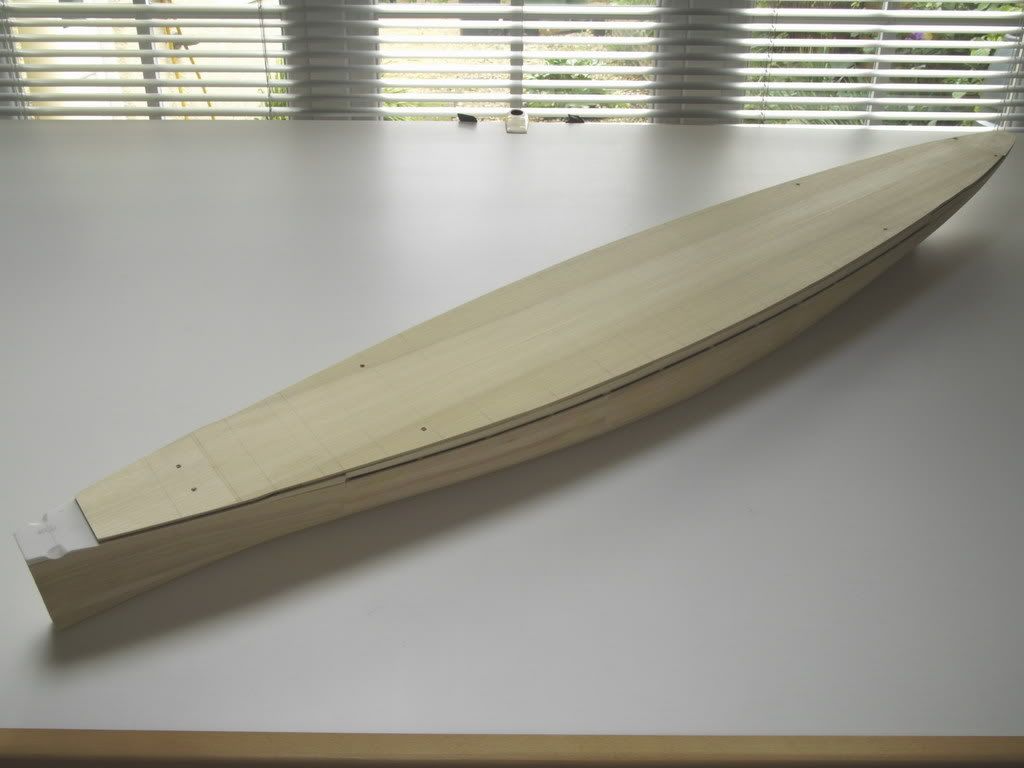
Next came the sanding; the night before attempting this, I hired-in extra virgins to dance naked around the garden at full moon; figured I needed all the help I could get! I used a power sander and aimed to reduce the edges back to the Amati deck (this is where the felt pen would have helped), levelling out to sand away a little of the edge of the 2mm layer. The bow and stern required the most removal, if fact back to zero at the very extremities.
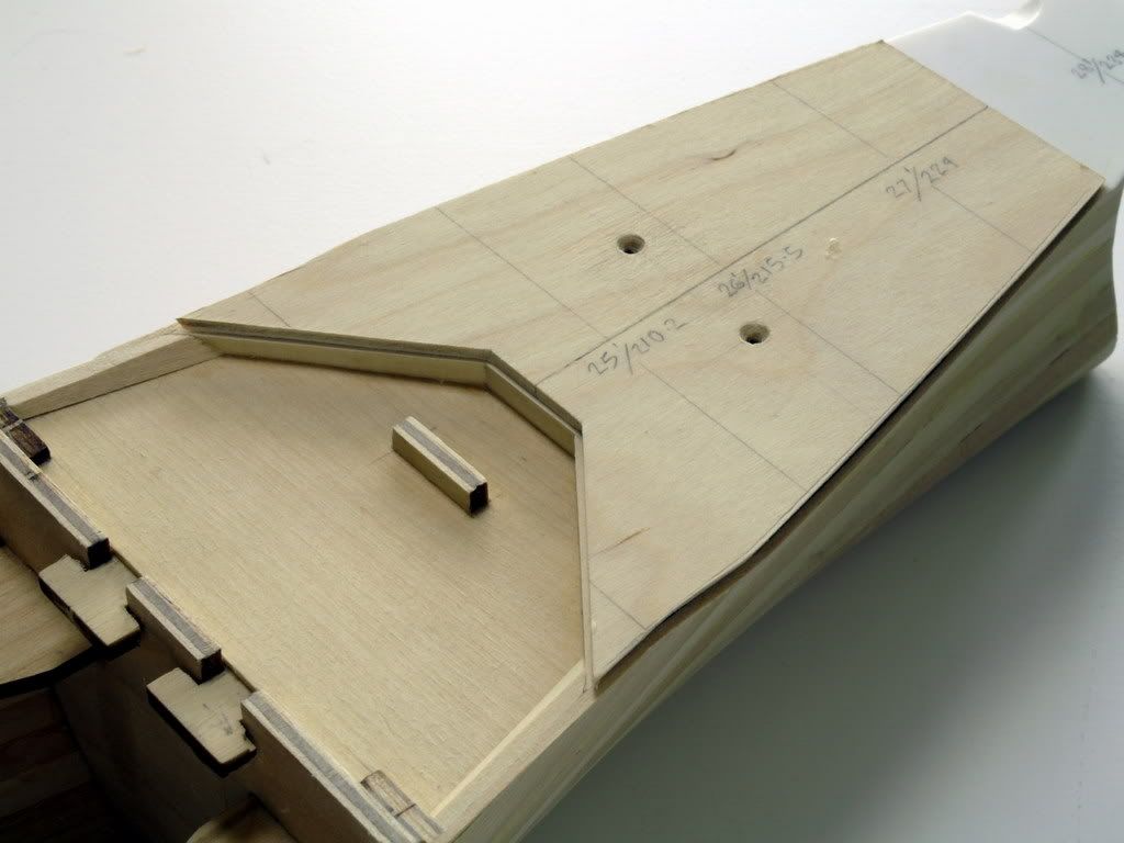
The profile was then checked against the Brower templates and pencil marks made where more material needed to be removed. The whole process took about 2 hours, during which I had several changes of underwear.
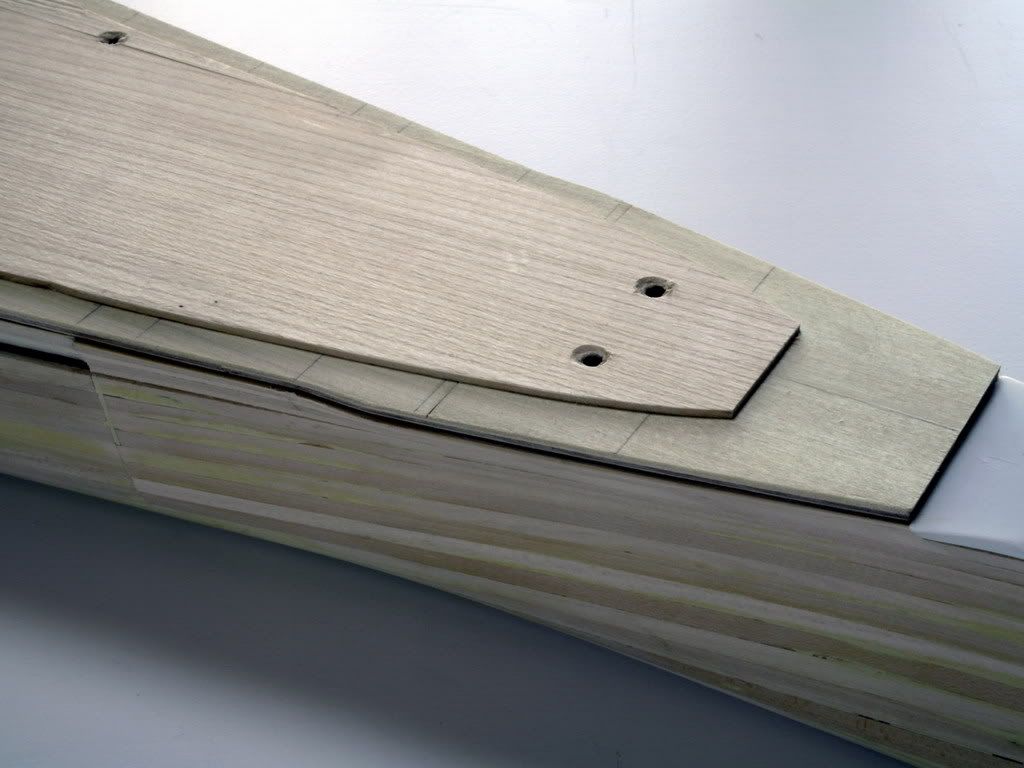
Unfortunately, I sanded too much off the bow so had to stick another layer of 1mm over the first 10cms to build it back up. Wood is so forgiving and the repair is scarcely noticeable. One great benefit of the cambering is the substantially increased rigidity of the deck, important for the r/c version.
The rest of my hull build is a hybrid of Markus’s r/c setup with the 2mm side-planking, which has had to wait until the deck camber is finished. Instead of the Amati cut, separating the fixed and removable decks, I opted to make the join invisible underneath the forward breakwater. This has the advantage of making turret ‘Anton’ completely accessible for motorisation after the foredeck is glued down; I haven’t finalised it yet but I want to give some time to further developing a way to stem ingress of water at this join.
Finally, I should say that all the above comes with a health warning. This is my first wooden build and I made some scary mistakes getting to this point, so if you want to take this route you must get the Brower book and be prepared to take your time with it. Incidentally, there seems to be a discrepancy between the cross-sections in the book and on the model, though not enough to affect the basic profiles of the deck. Good luck.
David
Another concern was whether the photo-etched parts would fit a curved deck. Taking the aircraft hangar on the upper deck (which is also cambered), on one of the first transverse PE parts to be issued, as shown on the German site, Amati have made the footings below the 2 doors deep enough for it to be accurately seated on the cambered deck. In other words, the bottom of inner sides of the doors sits closer to the deck than do the outer sides. The plan I devised therefore was to position the superstructures and draw around them an outline onto the deck, and then to remove wood from the high point of the camber sufficient to seat these items. OK, all this means a lot more work, but I guess none of us embarked upon the building this leviathan in the first place to save time!
So, satisfied that a camber wouldn’t prevent an accurate build, I decided that I’d need to build up the deck using plan 'J', laying down sheets of lime wood. This was the option I had been trying to avoid because it would be laborious and not a little risky, but in the end I couldn’t think of a better way. Firstly, I scanned the Brower book to 1:200 and made a complete set of cross-sections.
These were then cut out and positioned on the deck to establish the rough outline of the 1, 2 and 3mm contours. I first glued down a sheet of 1mm lime over the entire deck.
Only when it was too late did I think of marking the edge of the Amatie deck with a dark felt pen to help later when sanding down to the correct level. A second sheet of 2mm lime was then glued to the first layer, and as with the other, left to dry overnight with the deck screwed and weighted down.
Next came the sanding; the night before attempting this, I hired-in extra virgins to dance naked around the garden at full moon; figured I needed all the help I could get! I used a power sander and aimed to reduce the edges back to the Amati deck (this is where the felt pen would have helped), levelling out to sand away a little of the edge of the 2mm layer. The bow and stern required the most removal, if fact back to zero at the very extremities.
The profile was then checked against the Brower templates and pencil marks made where more material needed to be removed. The whole process took about 2 hours, during which I had several changes of underwear.
Unfortunately, I sanded too much off the bow so had to stick another layer of 1mm over the first 10cms to build it back up. Wood is so forgiving and the repair is scarcely noticeable. One great benefit of the cambering is the substantially increased rigidity of the deck, important for the r/c version.
The rest of my hull build is a hybrid of Markus’s r/c setup with the 2mm side-planking, which has had to wait until the deck camber is finished. Instead of the Amati cut, separating the fixed and removable decks, I opted to make the join invisible underneath the forward breakwater. This has the advantage of making turret ‘Anton’ completely accessible for motorisation after the foredeck is glued down; I haven’t finalised it yet but I want to give some time to further developing a way to stem ingress of water at this join.
Finally, I should say that all the above comes with a health warning. This is my first wooden build and I made some scary mistakes getting to this point, so if you want to take this route you must get the Brower book and be prepared to take your time with it. Incidentally, there seems to be a discrepancy between the cross-sections in the book and on the model, though not enough to affect the basic profiles of the deck. Good luck.
David