|
|
Post by markus on Jun 13, 2007 16:24:54 GMT 1
Marki, As I'm just at the stage of modifying pieces 37 & 38 can I assume this image below is correct? (please forgive the last minute chopping  )  The reinforcing plates are those hatched with red, and they are 2 thick, the remainder of the assembly is shown and the white portion is cut away? Is this right or have I got the wrong end of the stick ;D? image is correct !! additionally i made a cut above "used" to mount the receiver in the middle of the hull. this can be made afterwards if you intend to mount the receiver at the same place as i did markus |
|
|
|
Post by bob on Jun 13, 2007 17:21:39 GMT 1
Hi,
I took the plunge last night out came the drill, and although I had completed the first layer of planks around the hull including the stern I have managed to cut a hole through for a third prop shaft. I also drilled out part D as per insructions. I will spend a couple of days now cleaning up around the edges where I cut and fitting reinforcing bits to strengthen the area.
Marcus I will probably contact you at the end of next week with an order for the three motor kit. I dont get paid until the 23rd.
|
|
|
|
Post by Martin on Jun 14, 2007 10:17:31 GMT 1
Hi, I took the plunge last night out came the drill, and although I had completed the first layer of planks around the hull including the stern I have managed to cut a hole through for a third prop shaft. I also drilled out part D as per insructions. I will spend a couple of days now cleaning up around the edges where I cut and fitting reinforcing bits to strengthen the area. Marcus I will probably contact you at the end of next week with an order for the three motor kit. I dont get paid until the 23rd. Likewise i have already assembled up to and including part 11 is there any possibilty you can post some photos on the modifaction you have made. Fishtank |
|
|
|
Post by bob on Jun 14, 2007 17:08:22 GMT 1
Look at previous posts in this forum Markus has kindly detailed exactly what needs to be done to modify the hull for the third motor. You just need to take the pluhge and follow his instructions. Markus has also provided a lot of photos and instructions.
|
|
|
|
Post by Martin on Jun 14, 2007 21:34:16 GMT 1
Look at previous posts in this forum Markus has kindly detailed exactly what needs to be done to modify the hull for the third motor. You just need to take the pluhge and follow his instructions. Markus has also provided a lot of photos and instructions. Many Thanks looks like im going to be sticking to the 2 motor version i noticed some one else asked if the drag of a dummy 3rd propeller would make a diffrence which is perhaps what im considering as well. Fishtank |
|
|
|
Post by swanrail on Jun 14, 2007 22:51:30 GMT 1
I have now successfully installed the central motor/prop shaft in my model.
Unfortunately, by the time I had read Markus info on r/c, I had completed the "skeleton" and had three quarter planked the fore end and midships. Luckily, the stern only had two planks fitted.
Cutting out for the central shaft was a nightmare, as I had to modify parts 36 and 37 in situ ( a long hacksaw blade using cloth instead of a frame to hold it, was my solution, plus judicious use of a power file).
I drilled along a line as suggested by Markus from both the stern end and the midships end (my drill are normal length) upto 4.5mm diameter. In the centre, covered by part 38 my drills would not reach, so I burnt my way through with the aid of a hot nail.
Next was to drill the part D, i used a pillar drill to keep square, but had a problem trying to get the slope. (I propped up the lower edge on a piece of thin wood to get the angle, not very successfully).
Fastening in the motor assembly was straight forward, except I used wood screws from underneath to reinforce the glue joint, which if it became free through vibration could be a disaster,
I then attempted to line up the shaft to the motor, but found my 4.5mm too tight to set up correctly. I was then forced with great difficulty to widen the tube housing to Markus recommended 10mm, likewise I had to open up the fore end of part D for the same reason.
I am now happy with the alignment, as far as I can and have glued in the complete assembly, including part D. Hachette suggest leaving this until part 36, but I needed access to the shaft to make a watertight seal (using both resin and Araldite) before I can finish planking the stern.
I have run the motor under test and all seems well.
Conclusions: the parts 36/37 should be modified BEFORE building in. The shaft and part D need to be set up ASAP.
Foillow Markus excellant drawings and there should be no problems.
Shape motor housing to give motors slight downward slant (again see Markus photo).
The model is now very long and unwieldy, it is quite difficult working on the stern when the bow end has a mind of its own!
You need plenty of space to permit swinging round without damaging the ship, you or the furniture! It is also getting heavy, and I hope Hachette have allowed for this in the model, or else it will sink like the real thing on its maiden voyage!
Next job: the two shaft holes in part 39A are not big enough to fit the 4mm shafts, need to be opened up BEFORE stern planked.
|
|
|
|
Post by jimmy854 on Jun 14, 2007 23:21:35 GMT 1
this may be a silly question but how long are the shafts you are using ?? im only up to issue 6 but im planning in advance. hope this helps... 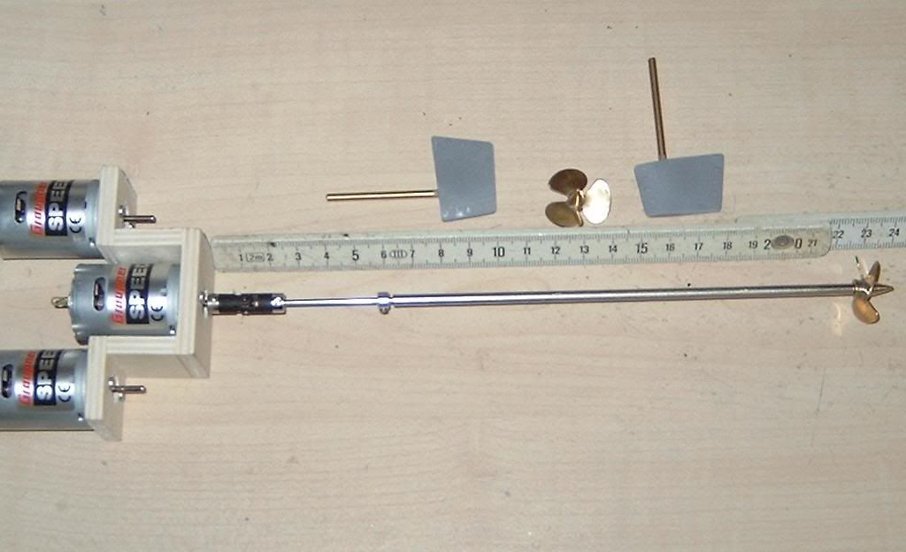 |
|
|
|
Post by swanrail on Jun 18, 2007 23:09:49 GMT 1
Here are 2 pictures of my model, first showing hull fully planked (first layer) and rubbed down smooth), the second the motors in place. 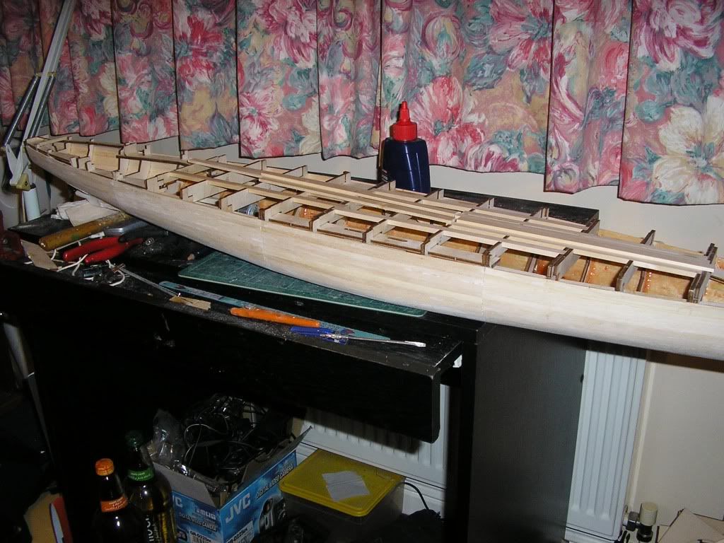 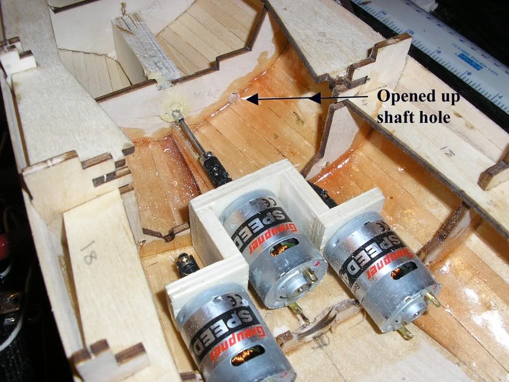 Also can be seen the expanded shaft holes and the hull lined with resin to waterproof. Part D has been permanently fixed to ensure watertight. |
|
|
|
Post by markus on Jun 23, 2007 23:13:33 GMT 1
Hello Markus Can you tell me wat size the propeller shaft is and the outside diam shaft tube please,as i think you may be able to you a oring to stop any water that might come up the tube. cheers paul shaft is 2mm, outside dia is 4mm an oring is not necessary because the shaft tubes have 2mm sinter bearings on both ends. a little grease inside the tube keeps any water out markus |
|
|
|
Post by swanrail on Jun 25, 2007 18:37:20 GMT 1
Today I have fitted the servo as supplied by Marcus, please note that in order for it to go in, I had to considerably reduce the stiffener shown as the left hand one on the previous page pictures, (between frames 39/40) to perilously near the prop shaft.
I had to use a power file in order to remove the surplus wood.
I am interested on how Markus fitted his, as his pictures show it in the same position, but he has not mentioned any need to cut out more wood in order to fit it.
|
|
|
|
Post by markus on Jun 25, 2007 19:51:37 GMT 1
Today I have fitted the servo as supplied by Marcus, please note that in order for it to go in, I had to considerably reduce the stiffener shown as the left hand one on the previous page pictures, (between frames 39/40) to perilously near the prop shaft. I had to use a power file in order to remove the surplus wood. I am interested on how Markus fitted his, as his pictures show it in the same position, but he has not mentioned any need to cut out more wood in order to fit it. i glued some planking strips onto the frames to get the necessary space (and additionally get the same height of all levers) this is also necessary to gain an even mounting surface for the servo due to different height of the corresponding frames sorry, i thought pics in page 4 were detailed enough to show the correct mounting of the servo, here more detailed pics... off topic: 2nd pic also shows nicely the rised second planking with the following advantages: 1. makes the separation edge of hull and removable deck invisible 2. makes it possible to mount the rail in the hull instead of mounting on different deck parts 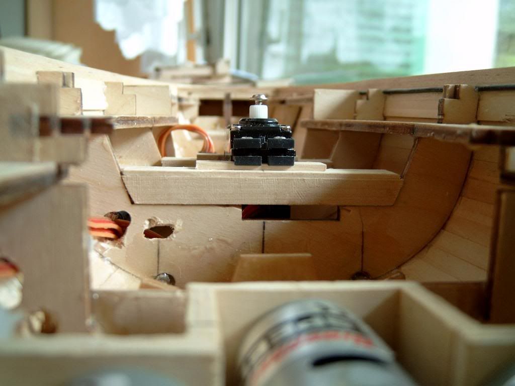 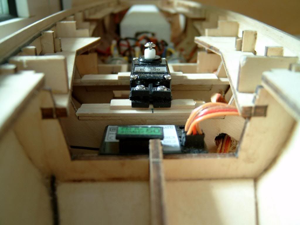 |
|
|
|
Post by swanrail on Jun 25, 2007 22:20:12 GMT 1
My servo must be deeper than yours! I had to grind out about 15mm of centre keel almost down to the prop shaft before I could fit to give a good clearance of the deck. Picture shows final fitting: 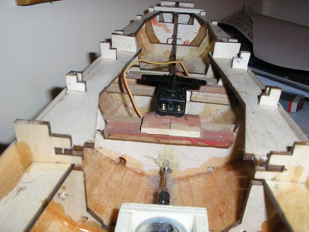 The servo arm lies 3mm higher than the bridging pieces between frames 13 to 43. |
|
|
|
Post by markus on Jun 26, 2007 8:45:37 GMT 1
hello don!
my servo has an overall height of 40mm without levers
i raised the lower frame by 12mm and the higher frame by 6mm to make the servo fit
markus
|
|
|
|
Post by markus on Jun 26, 2007 9:20:52 GMT 1
hello don! here again some detail pics. i also had to shorten the keel for the servo (pic1) but there is still plenty of space between servo and prop shaft (pic 2and 3) i have 3 different servos, all with the same height (+/- 2mm) markus 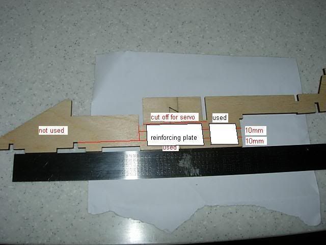 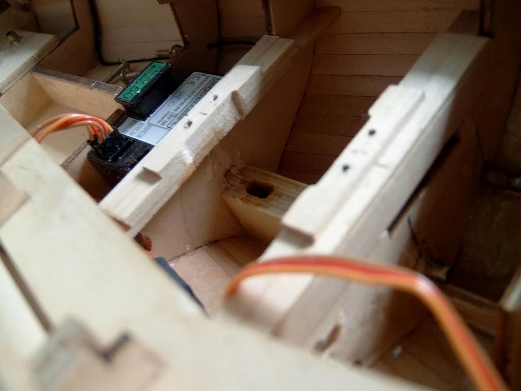 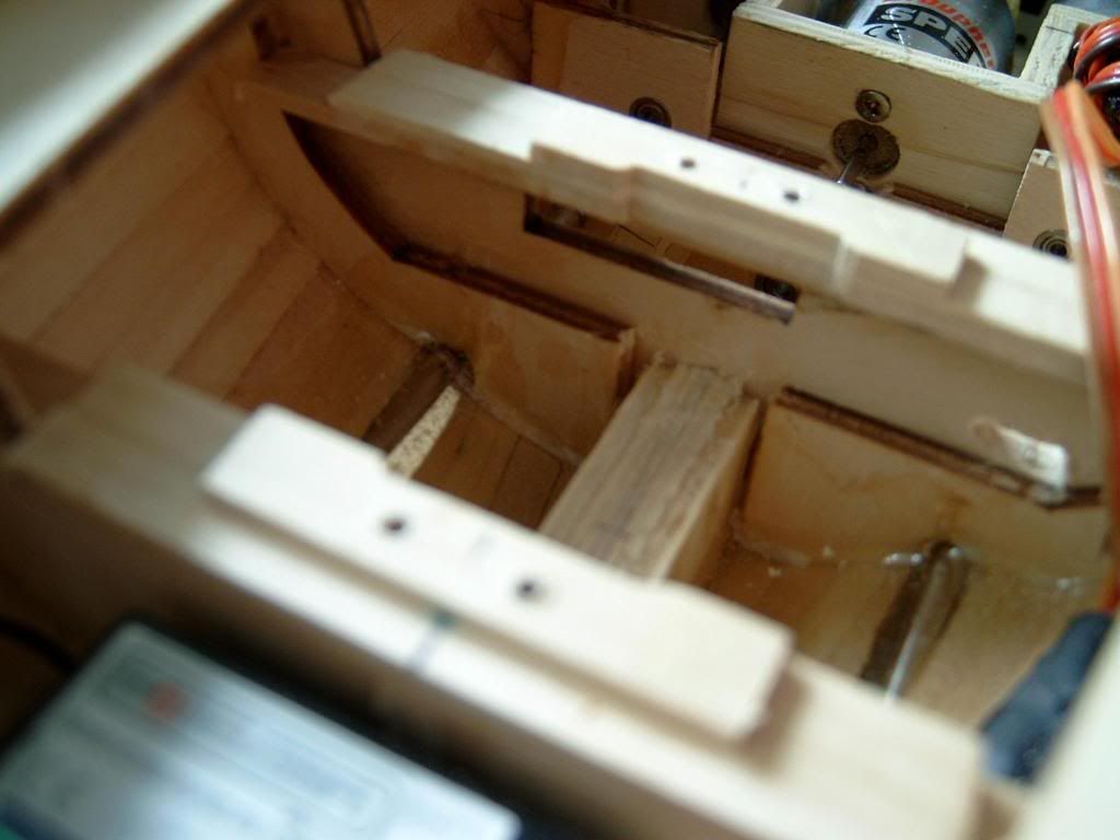 |
|
|
|
Post by bob on Jun 26, 2007 17:37:31 GMT 1
Hi guys order my motor set on Friday from Marcus. He contacted me today to say it is on its way. That is a really fast response ..... thanks Marcus.
For anyone wishing to contact him you can send a personal message on the board or email him click on his user name and you will find his email addresss.
|
|


 )
)