Post by swanrail on Oct 16, 2007 15:36:46 GMT 1
Having successfuly set up the prototype revolving gun turret with lifting guns, i am now sorting out on the model fittings.
Firstly, I have decided to stick to the mechanical lift. As much as I like Markus idea of lifting with a servo, I am not fully convinced that a. there is enough room, b. that the pivot system will work consistantly and c. there is access to the mounting screw on the servo top.
Please refer to the following diagram for the next part of the discussion:

Ref diag 1, this shows the turret as per the Anatomy of..... The barbette is glued to the deck, and is 5.5mm deep. it is expected that the deck overlay will be about 1mm thick. D is the diameter of the barbette, which is 55mm. C is the total height of the turret above the barbette and is 16.mm
A is the height above existing deck and is 9.25mm
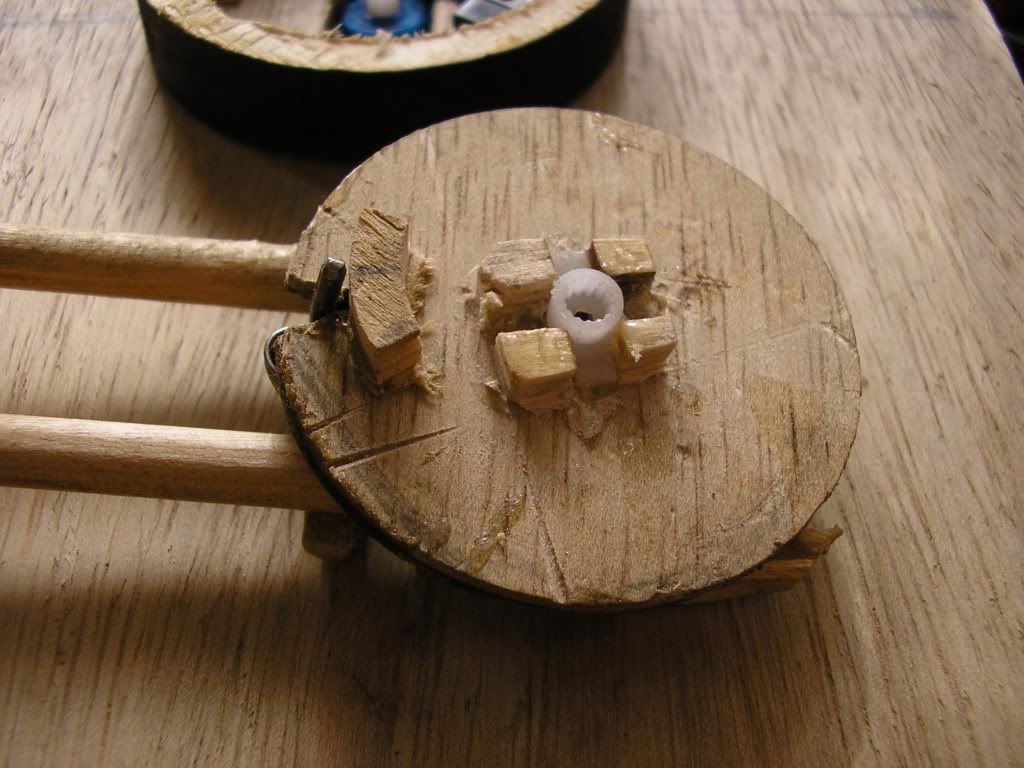
Diagram 2 shows the model needs. E is the rotating disk, which mine is 49mm being a suitable cutter I have. This allows the barbette, which goes outside it, to have a max. thickness of 3mm. The part shown in DIAG. 3 is the base for the rotating part and is also 49mm in diameter, with a width of 5mm. This will carry a 1mm thick brass strip on which the lifting pin will rub.
the guns will be pivoted on the centre line such that in their horizontal position they will be 9.25mm above the existing deck.
At a max of 30 degrees, the lifting pin will need to rise by 1cm providing that the pivot pin is on the centre line (20mm from central axis) To allow for this, the bottom of the centre line angles must be approx. 2mm BELOW the current deck level.(see F diag 3).
My gun turret Anton and Dora in particular will be mounted on another base plate the same diameter as the rotating plate. this will allow the assembly to be screwed to the deck and easily removed to service the servo. A small hole needs to be made to allow the lifting pin track to drop down below the current deck surface.
The centre arm of the servo will be mounted ABOVE the rotaing disk, with its boss coming out level with the underside. This the servo must be mounted (in my case on the bottom rotationg disk) such that the servo centre can mate properly with the boss.
The ring supporting the lifting pin track needs to be cut to permit the fitting of the two stop microswitches. This will allow a turn past 90 degrees of each side.
The full spec for the guns is:
Elevation plus 30 degrees. (also quoted as going down, but his not possible on my configuration)
Rotation plus minus 145 degrees on front turrets and 135 on aft turrets. Mine will be approx. 135 on all.
I can make up the system for Anton and Dora, but the guns and the pivots must be left until the parts turn up to see what problems they will bring!!!
Note that each gun barrel needs its own pivot assembly either side of the centre line, such that there is a gap between them permitting easy access to the servo boss fixing screw.
Firstly, I have decided to stick to the mechanical lift. As much as I like Markus idea of lifting with a servo, I am not fully convinced that a. there is enough room, b. that the pivot system will work consistantly and c. there is access to the mounting screw on the servo top.
Please refer to the following diagram for the next part of the discussion:
Ref diag 1, this shows the turret as per the Anatomy of..... The barbette is glued to the deck, and is 5.5mm deep. it is expected that the deck overlay will be about 1mm thick. D is the diameter of the barbette, which is 55mm. C is the total height of the turret above the barbette and is 16.mm
A is the height above existing deck and is 9.25mm
Diagram 2 shows the model needs. E is the rotating disk, which mine is 49mm being a suitable cutter I have. This allows the barbette, which goes outside it, to have a max. thickness of 3mm. The part shown in DIAG. 3 is the base for the rotating part and is also 49mm in diameter, with a width of 5mm. This will carry a 1mm thick brass strip on which the lifting pin will rub.
the guns will be pivoted on the centre line such that in their horizontal position they will be 9.25mm above the existing deck.
At a max of 30 degrees, the lifting pin will need to rise by 1cm providing that the pivot pin is on the centre line (20mm from central axis) To allow for this, the bottom of the centre line angles must be approx. 2mm BELOW the current deck level.(see F diag 3).
My gun turret Anton and Dora in particular will be mounted on another base plate the same diameter as the rotating plate. this will allow the assembly to be screwed to the deck and easily removed to service the servo. A small hole needs to be made to allow the lifting pin track to drop down below the current deck surface.
The centre arm of the servo will be mounted ABOVE the rotaing disk, with its boss coming out level with the underside. This the servo must be mounted (in my case on the bottom rotationg disk) such that the servo centre can mate properly with the boss.
The ring supporting the lifting pin track needs to be cut to permit the fitting of the two stop microswitches. This will allow a turn past 90 degrees of each side.
The full spec for the guns is:
Elevation plus 30 degrees. (also quoted as going down, but his not possible on my configuration)
Rotation plus minus 145 degrees on front turrets and 135 on aft turrets. Mine will be approx. 135 on all.
I can make up the system for Anton and Dora, but the guns and the pivots must be left until the parts turn up to see what problems they will bring!!!
Note that each gun barrel needs its own pivot assembly either side of the centre line, such that there is a gap between them permitting easy access to the servo boss fixing screw.