Post by swanrail on Mar 30, 2008 0:44:19 GMT 1
I am now finishing off my deck planking for the stern superstructure. I noted from the model by Peter Benheim (http://www.bismarck-class.dk/shipmodels/german_models/bismarckbeisheim.html)
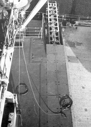
that there is a sloping deck from piece 241 to hangar No. 1.
I modified piece 241 by sanding the after edge at an angle to line up with the triangular wedges, filled in between these wedges with scrap wood to make a solid base, added margin planks and then decked over.
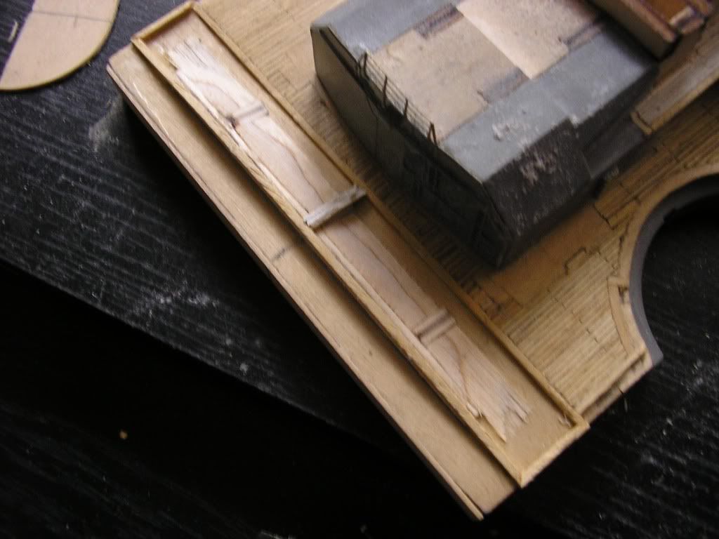
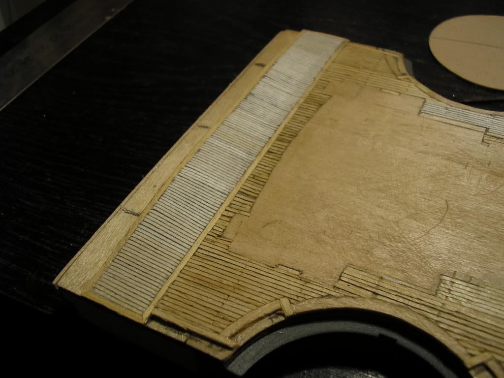
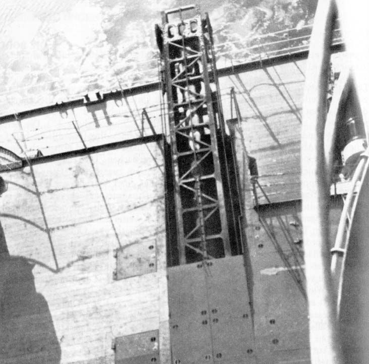
I then decided to make up the catapaults as I wanted to check that they would lie under the deck level at the centre, where there will be a metal plate. (TIP when making these up, leave off the top section until the inside has been painted, then glue on, else impossible to get paint internally!!)
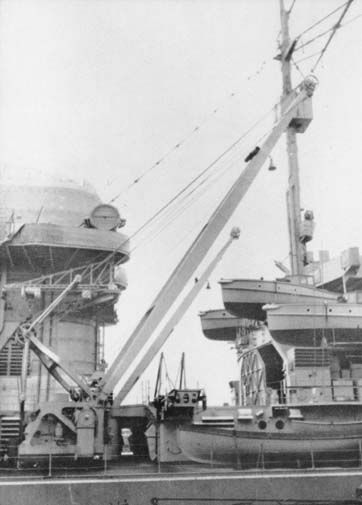
To see how these fitted, I referred to Peter model, which suggests the walkways at each where left open (the Hachette ones have end rails), but worse was to follow: the builders model of the ship shows the catapaults with NO sidewalks at all, and this was confirmed by several other models!!
If anyone has any definite proof on how these were fitted, and I would also be grateful if anyone can tell me how they worked!!!,
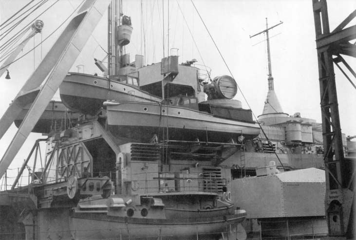
Also noted that the builders model and some others had the two wheels set closer to the superstructure than ours.
I have waded through hundreds of pictures of the real ship, but cannot find one with a clear view of this area.
Also interesting, Jack Brower in his Anatomy book fails to mention or show the catapaults at all, and the side views he has do not help either.
that there is a sloping deck from piece 241 to hangar No. 1.
I modified piece 241 by sanding the after edge at an angle to line up with the triangular wedges, filled in between these wedges with scrap wood to make a solid base, added margin planks and then decked over.
I then decided to make up the catapaults as I wanted to check that they would lie under the deck level at the centre, where there will be a metal plate. (TIP when making these up, leave off the top section until the inside has been painted, then glue on, else impossible to get paint internally!!)
To see how these fitted, I referred to Peter model, which suggests the walkways at each where left open (the Hachette ones have end rails), but worse was to follow: the builders model of the ship shows the catapaults with NO sidewalks at all, and this was confirmed by several other models!!
If anyone has any definite proof on how these were fitted, and I would also be grateful if anyone can tell me how they worked!!!,
Also noted that the builders model and some others had the two wheels set closer to the superstructure than ours.
I have waded through hundreds of pictures of the real ship, but cannot find one with a clear view of this area.
Also interesting, Jack Brower in his Anatomy book fails to mention or show the catapaults at all, and the side views he has do not help either.