|
|
Post by Achtung!! on Aug 10, 2009 10:34:38 GMT 1
Nice one.
|
|
|
|
Post by coenie on Aug 10, 2009 11:45:13 GMT 1
Ok now that I sorted out the way to share my photos, here is an example of the LED's already in place. You'll see that I placed them as such that light will emmit through all portholes in the area surrounding the LED's. I tested it and looks good accept it must be quite dark. I reckon if you place to many LED's the Bissy will look like a Christmas tree. 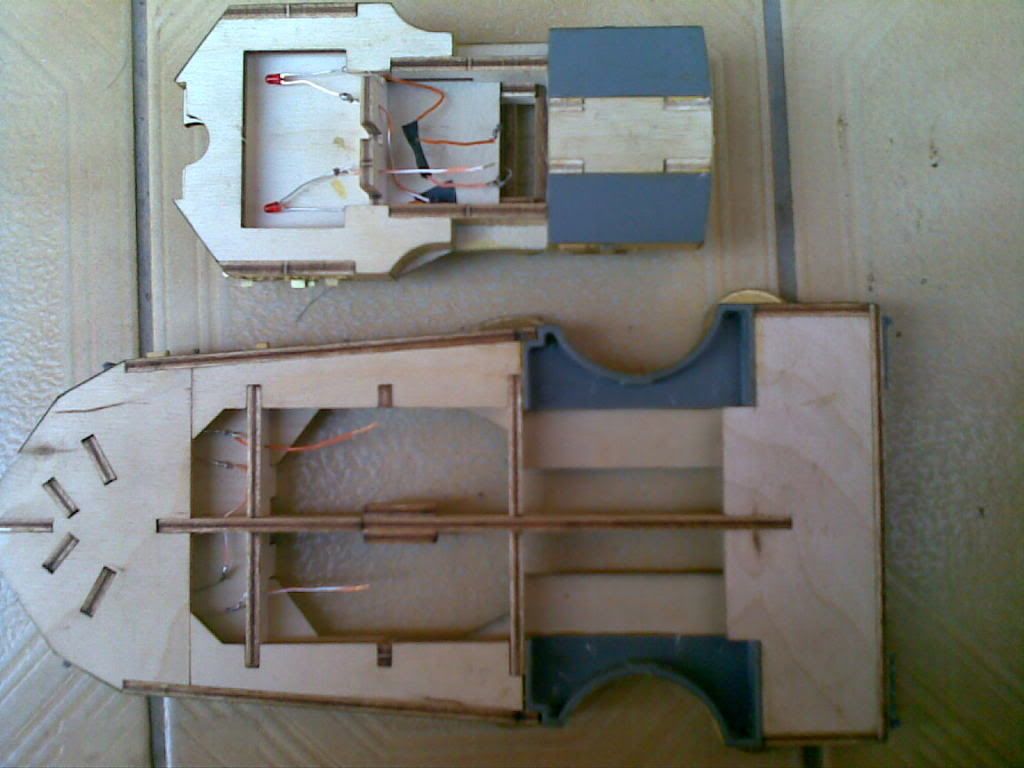 |
|
|
|
Post by Achtung!! on Aug 10, 2009 12:15:26 GMT 1
What size are the LEDs you have used?
|
|
|
|
Post by coenie on Aug 10, 2009 12:27:52 GMT 1
Lenght = 5mm x Diametre = 3mm (the wire shoulder leading out of the LED is 4mm from side to side) Voltage per LED = 2.2 volt.
|
|
|
|
Post by coenie on Aug 10, 2009 14:31:46 GMT 1
Alright here's my try on the suggested wiring diagram. Hopes it make sense. Like to hear you guys suggestions on the problem I stated under my NOTE. Another thing to note is that we can add more series circuits as we need because all circuits will end in one parallel circuit at the transformer. 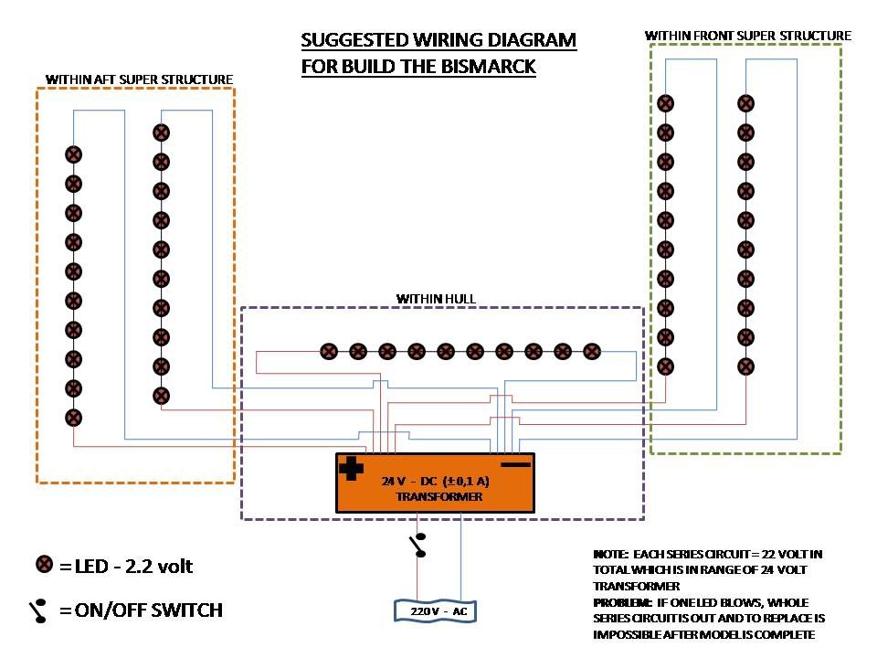 |
|
|
|
Post by Achtung!! on Aug 10, 2009 15:42:41 GMT 1
Ta for the wiring diagram. Now I'm not an electrician, but noticed you have an external 220v ac supply. Are you indicatiing these LEDS cannot be lit without being connected to the external 220vac supply. Might be a bit dangerous sailing the boat with a mains cable trailing across the pond!
Also you made reference to once one LED goes , whole lot goes. Considering I may have upto five lights on my boat I think I might have to re-think a way of being able to disconnect one if one of the LEDs go.
Ah well still struggling with getting the LEDs in one of my lights to see if it does work. Worry about running later on !
Have a K for all your hard work.
|
|
|
|
Post by coenie on Aug 10, 2009 17:56:12 GMT 1
Thanks Achtung as well for a good laugh on the mains cable in the water.
You're right, the diagram is not for the oaks who wants to sail their Bissy, but if they can connect any battery that supply the voltage needed, it will work just the same.
The only catch is the number of LED's in a series circuit must add up to the amount of voltage needed. Example 3 LED's of 2.2 volt in series will need at least 6.6 volt to lit up.
The source must therefore be rather a volt or two higher than the required need in the circuit, even half a volt lower will not smoke the pipe.
The one LED that goes will only cause the group in that spesific series circuit to go under with it and not to say they are dead, but the dead LED now causes a break in the circuit.
The other series circuits will still function, remember they are in parallel circuits, which mean they all get the power as long as the spesific series circuit stays complete (w.o.w. no dead LED's or lose connections).
Another thing to keep in mind is not to go to high with the input voltage, this will blow your LED immediately.
So if you only got five LED's and they require 2.2 volt each, you must either place all in one series circuit and light them up with a 12 battery or you must go one by one with maybe two 1.5 volt dry cell batteries powering all five (or more) in a parallel circuit.
I hope I made sense with all this technical talk.
|
|
|
|
Post by Mike B on Aug 10, 2009 19:55:14 GMT 1
If you use standard 3mm or 5mm LED's, you can use any voltage on them - even 220vAC. The criteria is the operating current. Normal LED's work best at between 10-20mA. Therefore, using Ohms' law (I=E/R) or (R=E/I), using a 680 ohm resistor and 12v supply, the LED will draw 17mA. (0.017 in the formula).If you use a 1K0 resistor, the LED will draw 12mA and not be as bright. If you use a 6v supply and a 680 ohm resistor, you will draw 8mA and the LED will not be very bright. To overcome the problem of an LED failing, all the LED's and their resistors should be wired in parallel. This also obviates the need for separate groups of circuits. LED's can be added at any time. Work out the current draw of one LED and resistor, multiply it by the number of LED's used and that is the current draw from your power source. The resistors used need only be 1/4 WATT. 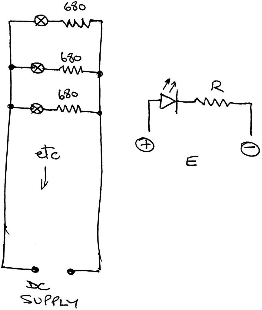 |
|
|
|
Post by coenie on Aug 12, 2009 16:04:20 GMT 1
Thanks Mike B, never thought of including resistors, but will definitely be going back to the drawing board with your suggestion.
|
|
|
|
Post by Achtung!! on Aug 12, 2009 16:52:06 GMT 1
Been having a bit of a think about the lights and being able to 'plug and play' the LEDs let me have a think and bit of experimenting.
|
|
|
|
Post by swanrail on Aug 12, 2009 23:30:11 GMT 1
Going a step further, you can buy LEDs with the resistors fitted inside the plastic case, ie with the 3mm LED it is still 3mm including the resistor. They work over an operating range of about 6 volts to 18 volts with the same resistor. Much easier to wire up and no problems if your maths goes wrong!
Maplins sell them, as well as specialist web site if you do a searcg for LEDs. (found one which even sells downlighters for 230v AC to replace standard ones!).
|
|
Deleted
Deleted Member
Posts: 0
|
Post by Deleted on Aug 13, 2009 13:14:21 GMT 1
I'll do some experimenting with my superstructure and leds. When I can find my solering iron. - LoL ;D
|
|
|
|
Post by coenie on Aug 16, 2009 11:16:40 GMT 1
I also called in the help of an electronic expert and he informed me that we can go both directions, but we must take note that we work with heat if we go to high on the voltage input. We must rather take note of the voltage needed and work out as mike B said, the amount of current to be sure of the brightness of the LED's. We must however ensure that DC power is the final feed to the LED's and not AC.
He also said that LED's are very durable and will not blow easily, so if we go for the series circuits as mentioned previous and don't use them in the on position day and night, we shall have the pleasure for many years.
|
|
|
|
Post by russ on Dec 26, 2009 23:37:33 GMT 1
Coenie cani ask what program you use for your marvolous Wiring diagram as, i could do with using that to do a Bikes wirign Diagram
|
|
|
|
Post by matt on Dec 27, 2009 17:48:28 GMT 1
hello Don. Where did you find the information on the 230v down lighters please? I also remember the maplin LEDs with the resistors. I fitted them in the Victory. Looked good. I cannot make up my mind about the Bismarck. After all she would be running with no lights showing.
Matt
|
|