|
|
Post by viking on Apr 2, 2007 17:11:26 GMT 1
pay attention - most of these wonderful parts are unfortunately for 1:100 models but his rudders and props in 1:200 are simply great... markus you will not find the props no the site as thay are a special but you can get in touch with lasskes by E,Mail Modellbau-Lassek@t-online.de i am just waiting to hear back on P.P> should hear in the next day or 2  john |
|
|
|
Post by markus on Apr 5, 2007 16:40:31 GMT 1
after receiving the second order from UK i decided to translate the mounting instructions for the british bismarck builders. here's what to do: 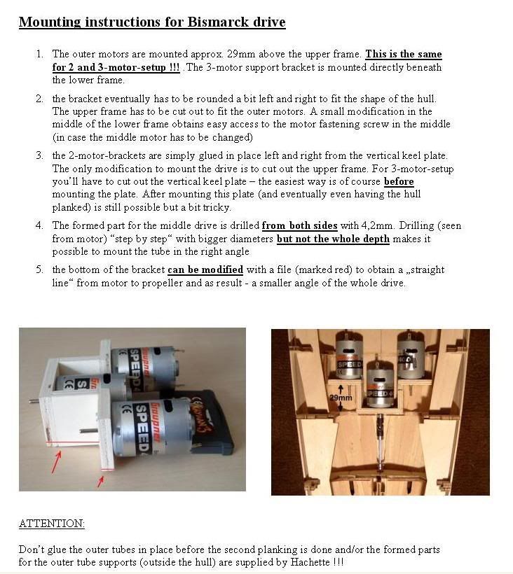 |
|
|
|
Post by markus on Apr 6, 2007 11:45:16 GMT 1
the angle of the tube is of course not as big as shown by the red marks.... the middle drive has a height difference of 8mm between motor and prop - on a length of 23cm. that makes an angle of only 2 degrees. the angle of the outer tubes is slightly smaller because these props are mounted 2mm higher than the inner prop original layout can be seen here: www.bismarck-class.dk/technicallayout/rudders_propellers/rudders_propellers.htmlmarkus |
|
|
|
Post by viking on Apr 6, 2007 15:45:38 GMT 1
from Lassek's [The price for the brass ship's propeller for Bismarck 1 / 200 (three ship's propeller with shaft M 2) is 39 € (EURO) plus postage.
The price for the rudder-blades for Bismarck 1 / 200 (two rudder-blades) is 12 € (EURO) plus postage.
The postage cost to UK is 20 € (EURO). ] if you are going to order from them or Markus and you are going to do it by check it will cost them to have it cashed so pleas add 2 or 3 EURO to the cost Markus will shout at me for saying it, but i think it is only fare to help cover the banking cost.IT is cheaper than paying £25 as my bank wanted to charge me to send the money .
|
|
|
|
Post by markus on Apr 6, 2007 16:25:20 GMT 1
..Markus will shout at me for saying it... no problem, my bank is just 100 meters from me... markus |
|
|
|
Post by markus on Apr 14, 2007 20:04:00 GMT 1
and that's how it looks with all shafts glued in place... 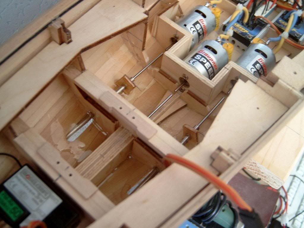  |
|
|
|
Post by viking on Apr 17, 2007 14:41:24 GMT 1
hi campers am happy as a bug in a rug got my motors and things from MarKus yesterday and very fine they are thank you Markus ;D john
|
|
|
|
Post by viking on Apr 20, 2007 13:00:48 GMT 1
Question Markus have you reinforced all the stern to accommodate drilling for center prop shaft . ie from 39/a to where the shaped bit gos Think this has to be dun to retain strength of keel john
|
|
|
|
Post by markus on Apr 21, 2007 13:37:18 GMT 1
Question Markus have you reinforced all the stern to accommodate drilling for center prop shaft . ie from 39/a to where the shaped bit gos Think this has to be dun to retain strength of keel john yes, i reinforced it with wooden plates on both sides along the keel plate, but i didn't drill into - i just shortened and cut the keel plate out BEFORE i glued it in place.. note that these cuts should have a space of approx. 10mm. so you can mount the tube in the right position. this cut lies in range from approx. 10 to 20 mm above the lower plate markus |
|
|
|
Post by Don butler on May 7, 2007 23:41:55 GMT 1
Hi Markus, thanks for the info on the R/C gear. Would it be possible to give the measurements to build the motor housing (for 3 motors) and also how to mark up parts 36/37 to enable cut for prop tube?
Thanks
Don
|
|
|
|
Post by markus on May 8, 2007 13:03:03 GMT 1
Hi Markus, thanks for the info on the R/C gear. Would it be possible to give the measurements to build the motor housing (for 3 motors) and also how to mark up parts 36/37 to enable cut for prop tube? Thanks Don no problem - the motor housing consists of 5 wooden plates glued together 1 piece 45 / 30 mm 2 pieces ?? mm (depending on thickness of wood) / 30 mm 2 pieces 30 / 30 mm the holes for fastening the motors and the shafts depend on the used motors. the keel plate has to be cut out at range from 10 to 20mm above the lower wooden plate. you may also obtain the complete set with motors mounted in the housing, shafts, tubes, propellers and cardan joints ready to built in. just ask user "viking" - i think he is quite satisfied with my delivery markus |
|
|
|
Post by Mikey on May 18, 2007 0:19:55 GMT 1
I'm trying to decide whether to go 2 or 3 motors on my model. At the moment I'm somewhat unsure of the modifications needed for the center prop shaft.
Is it possible to get a diagram of the aft keel plates that show the dimensions for modification?
If not, how will having only 2 props affect steering, speed, reversing, etc over 3 props?
|
|
|
|
Post by Mark on May 18, 2007 3:38:45 GMT 1
I'm going to hazard a guess (and it is only an educated guess) that there won't be very much difference between a 2 or 3 motor set-up. R/C model ships are generally over-powered, and in any case, you could always fit more powerful motors if you find that it is a bit sluggish. It shouldn't make too much difference to the steering when going ahead as the two rudders are in the wash of the outboard props. The centre prop is unlikely to make any difference to the steering. Model boats never seem to handle very well when going astern, and I don't think that the centre prop will make much difference.
I'm going to go for a two motor set-up. If it seems underpowered I shall fit more powerful motors. If steering is a problem then I shall fit independent speed controllers to each motor and mix them with the rudder. In simple terms, when you move the rudder, say to the left, the right motor will speed up and the left motor will slow down. This will help the model turn much quicker. Markus is selling this. See his entries earlier in this thread. He also mentions the difference between 2 or 3 motors.
|
|
|
|
Post by markus on May 18, 2007 7:38:47 GMT 1
I'm going to hazard a guess (and it is only an educated guess) that there won't be very much difference between a 2 or 3 motor set-up. R/C model ships are generally over-powered, and in any case, you could always fit more powerful motors if you find that it is a bit sluggish. It shouldn't make too much difference to the steering when going ahead as the two rudders are in the wash of the outboard props. The centre prop is unlikely to make any difference to the steering. Model boats never seem to handle very well when going astern, and I don't think that the centre prop will make much difference. I'm going to go for a two motor set-up. If it seems underpowered I shall fit more powerful motors. If steering is a problem then I shall fit independent speed controllers to each motor and mix them with the rudder. In simple terms, when you move the rudder, say to the left, the right motor will speed up and the left motor will slow down. This will help the model turn much quicker. Markus is selling this. See his entries earlier in this thread. He also mentions the difference between 2 or 3 motors. my first test with the titanic 1:200 was a 2-motor-setup (same parts as used now for the bismarck). the ship was quite fast, even when powered with only 5 cells. unfortunately the titanic's rudder was much too small for the length of the ship . the bismarck's rudders are a bit small, too - and the rudders end at height of the prop shaft. i think we have the same problem again... so i mounted 2 switches at the rudder lever to switch the inner motor off when steering. it went a bit slow when turning, but turning diameter was ok - only for some minutes, then the switches (10A-versions) melted away...  then i decided to solve the problem with electronics - results with v-mixer were really good, i was only disappointed of the half speed when fully turning (because of driven only with outer prop, inner prop proprtionally slowed down). so i motorized the middle prop - because this motor is not affected by the mixer. turning at almost full speed was no problem anymore. handling the ship was really fun now - no matter if forward or backward. and with 7,2V it was incredibly fast - since then i was never again overtaken by those 10-year-old boys with their 20-euro-toy-boats ;D ;D markus |
|
|
|
Post by markus on May 18, 2007 11:30:42 GMT 1
...and here the necessary cuts for the middle drive this is done best before mounting it. after cutting simply glue 4 wooden plates ( 2 on each side) over the cut to reinforce this part. the tube can be mounted later in the desired position. due to the wood thickness of 4mm (like the tube) the tube is automatically positioned in the middle of the hull i also made a cut at the upper "used" section directly above the cut to mount the servo there. this is not necessary but i think it's the best "location" to mount the servo. pics somewhere here in the forum... @mark: hope you don't mind i used your pic for this 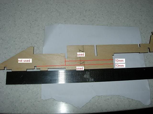 markus |
|

 john
john