|
|
Post by Mark on Dec 4, 2007 6:45:37 GMT 1
Build in situ. I just put scraps of printer paper underneath the glue joints.
Soooo many ways to skin a cat.
|
|
|
|
Post by ph on Dec 4, 2007 13:41:42 GMT 1
Cheers for the help
soon as iv done the planking im gona start on the super structure
|
|
|
|
Post by markus on Jan 5, 2008 14:10:12 GMT 1
here's some superstructure progress spent most of the time removing superglue from my fingers...    |
|
|
|
Post by jason on Jan 5, 2008 14:44:00 GMT 1
Looks excellent,things are taking shape quicker every week. We are about two weeks away from spraying the hull. Have you got any tips on how you guys in Germany have done yours and colour scheme (sanding/filling/spraying etc)
|
|
|
|
Post by markus on Jan 5, 2008 15:38:46 GMT 1
i applied 2 coats of glattfix onto the inside and 4 coats onto the outside of the hull. sanded the outside of the hull after each coat of glattfix. to my surprise i didn't have to use any filler  by now there's only 2 coats of grey spray primer (synthetic resin paint) applied to the hull markus |
|
|
|
Post by trevor on Jan 5, 2008 19:01:29 GMT 1
Hi Marki53, excellent pictures, however I notice that your decks is inside and slightly below hull planking whereas in the instuctions with the magazine it says to plank to below deck level. I must say your way looks much better so could you please advise me on how high above your deck the hull planking goes, it looks about 1 to 1.5 mm and looks like 1.5 mm thick, I have already started the second planking as of issue 36, your help would be much appreciated.
|
|
|
|
Post by markus on Jan 5, 2008 21:59:21 GMT 1
Hi Marki53, excellent pictures, however I notice that your decks is inside and slightly below hull planking whereas in the instuctions with the magazine it says to plank to below deck level. I must say your way looks much better so could you please advise me on how high above your deck the hull planking goes, it looks about 1 to 1.5 mm and looks like 1.5 mm thick, I have already started the second planking as of issue 36, your help would be much appreciated. i decided to modify a bit and used full planks with 8x2x1200mm above and 5x1,5x1200mm below the recess.. yes, it's about 1-1,5mm higher than the deck. afterwards the planks will be flush with deck level (when veneer is glued onto the deck) posted details somewhere in the 'hull' thread markus |
|
|
|
Post by swanrail on Jan 6, 2008 0:16:40 GMT 1
Having seen some of Markus's earlier pictures, I recently decided to do the same. In my case, as the side planking was already in place, I have edge glued a 5 x 1mm strip over the top, and have reduced the deck by 1mm in width each side.
The new top section lines up perfectly with my stern filler, and once the proper deck has been laid, then the side pieces will sand down level with the veneer.
In my case, I shall fit the ships rails to the removable deck (waterways) and not to the extension piece. This fits the cross section drawings in the Anatomy book, where the rails are slightly inside. It also makes the rails less prone to damage when the removable deck is removed to get at the "engine" room!!!
|
|
|
|
Post by markus on Jan 6, 2008 11:55:37 GMT 1
i know about the danger of damaging the railing when removing the deck. that's why i have decided to place main switch, charging jack and smoke generator in the superstructure so i don't have to remove the deck everytime i run the ship electrical connection can be done by some kind of plug/socket system, see example pic a separate plug/socket could be used for the antenna wire....  |
|
|
|
Post by eric on Jan 6, 2008 23:51:41 GMT 1
Having seen some of Markus's earlier pictures, I recently decided to do the same. In my case, as the side planking was already in place, I have edge glued a 5 x 1mm strip over the top, and have reduced the deck by 1mm in width each side. The new top section lines up perfectly with my stern filler, and once the proper deck has been laid, then the side pieces will sand down level with the veneer. In my case, I shall fit the ships rails to the removable deck (waterways) and not to the extension piece. This fits the cross section drawings in the Anatomy book, where the rails are slightly inside. It also makes the rails less prone to damage when the removable deck is removed to get at the "engine" room!!! Hi Don, would you be able to post a pic or two of the mods you've made to the hull? especially around the forward area, I have been toying with the idea of following Markus' lead here too, but am not sure how to do the bow area. Cheers, Eric. |
|
|
|
Post by swanrail on Jan 7, 2008 0:14:34 GMT 1
Hi Eric,
will try to do tomorrow. Basically, the extension sides cover the whole of the removable deck parts plus the stern, including around the new part 70.
At the bow end, I have left as is. When the time comes, I shall make the deck with the 1mm strip planking, and sand down to about 0.75mm thick. This will extend upto the sides of the fo'cstle.
Hachette have left some confusion in this area, as following their instructions, the side planks end just below the ply deck, leaving a vertical straight part.
By studying the Anatomy book (with a magnifying glass!!) and also looking at the picture on the front cover of the mag, I have realised that the vertical part needs to be sanded back to form a bevel. This I will do once the decking is complete.
The same applies to the side extensions, when they are sanded level with the deck planking, the outside edge also needs to be bevelled at about 45 degrees. This means, of course, that the ships rails need to be fitted to the removable bit, which again agrees with the "book".
|
|
|
|
Post by popeye on Jan 7, 2008 18:10:53 GMT 1
I will be doing something similar to Mark in terms of controls. I have waterproof switches, which will be fitted through the fixed forward deck and/or the rear deck (over the rudder gear) to isolate the batteries and switch the radio control gear on and off without having to open up the main deck. I will also have mini circuit breakers in the motor line (set to trip at about 20A - the motor stall current) that will fix through the deck. There will also be a little line of high intensity LEDs through the front deck so that I can see from a distance (i.e. when the ship is out on the water) that there is electrical power to the motors and radio control (the motor LEDs are dual colour to show whether the motor is going ahead or astern). I might fit these onto the superstructure but will make the decision on this when the model is near completion.
|
|
|
|
Post by swanrail on Jan 7, 2008 18:21:39 GMT 1
As requested: Shows side walls with decks removed: 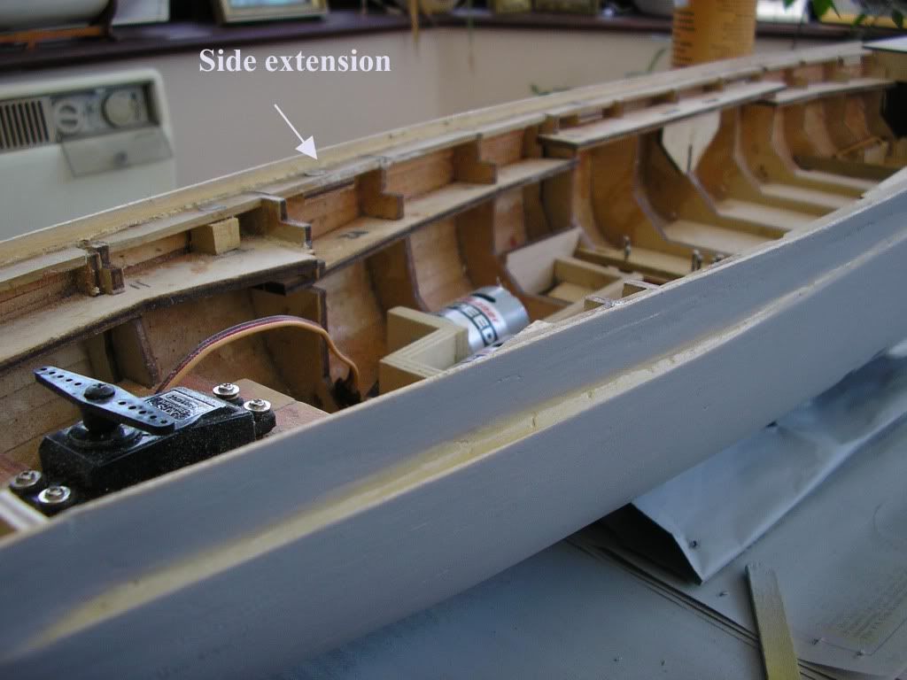 and with decks fitted: 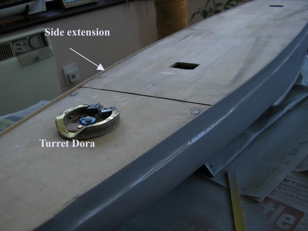 note that these extension pieces will be sanded down to be level with the deck when fully planked, and the outside edge bevelled as per my diagram below: 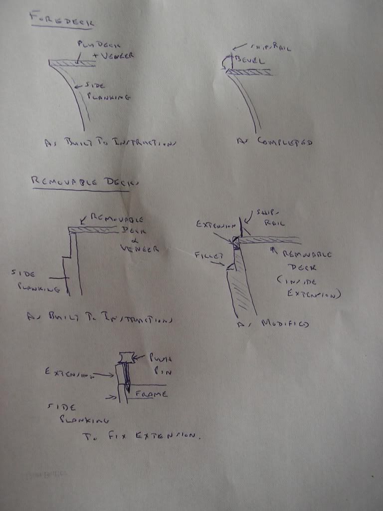 the bottom drawing shows how I fixed the extension plank in place. I used push pins (large map pins) on each frame, fitting the pin as close to the original planking as possible. The new plank was then coated with Evostik waterproof glue on its bottom edge and put into place. It was then clamped firmly by pushing down hard on the push pins and left for 24 hours. This technique ensures the new plank was in alignment with the plank below and held tightly in place to make a strong joint. |
|
|
|
Post by nm on Jan 7, 2008 19:02:16 GMT 1
|
|
|
|
Post by nm on Jan 7, 2008 19:05:01 GMT 1
Oops again.
That's 9.49 euro.
NM
|
|