|
|
Post by popeye on Sept 22, 2008 11:47:12 GMT 1
This is Popeye's build information for his Bismarck. I thought it about time as I leave enough info in other people's areas.
|
|
|
|
Post by popeye on Sept 22, 2008 12:01:05 GMT 1
I keep all my pictures of the Bismarck, Yamato battleship and its steam plant, my train and my Orrery (Build a Model Solar System) on the following site: www.flickr.com/photos/commander-popeye/The picture are arranged in sets, so you can see groups of photos for particular points in the build (e.g. the Mast). I have just finished adding the brass portholes to the hull (3.5mm diameter from The Model Dockyard), they look superb and I will post pictures on the Flickr site shortly with details of how I prepared the hull and fixed the portholes in. |
|
|
|
Post by markus on Sept 22, 2008 12:29:54 GMT 1
like your ship holder, good idea  markus |
|
|
|
Post by popeye on Sept 26, 2008 16:05:15 GMT 1
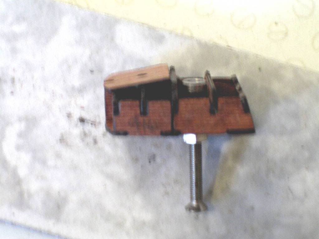
I have updated my Flickr site with the pictures of the fitting of the portholes to the hull and making my ship holder/launcher mobile (so I don't even have to carry it across the grass to the pond !) with the addition of wheels, see the set called "Bismarck Hull Portholes" at www.flickr.com/photos/commander-popeye/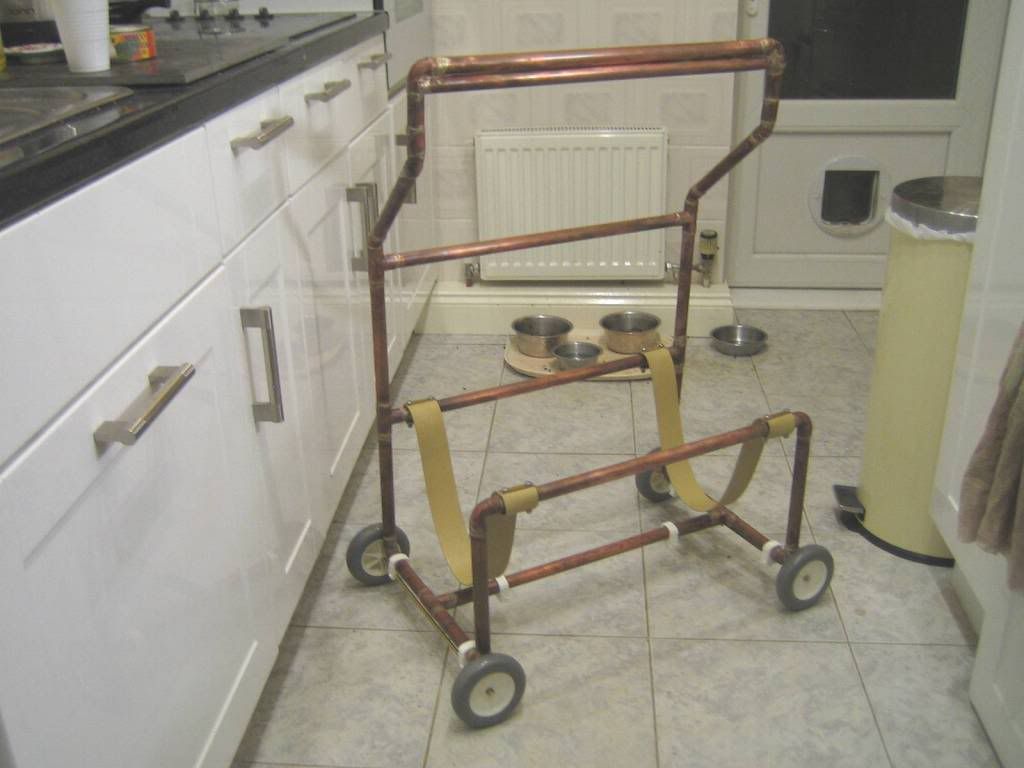 The wheels (from my local do-it yourself) are all plastic and mounted on a 6mm brass shaft, held in position with m2.5 stainless steel bolts and nuts. The wheel sets are fitted into holes drilled into 22mm plastic fittings (the white bits you can see clamped to the tubing), normally used to fix the 22mm copper tubes to the wall (as part of the household water fittings). This means that the wheels etc., can be safely immersed in the water (without anything going rusty or corroding) when the ship holder is launching a ship in the water. Full details of the ship holder and its building can be seen on my Flickr site (as above) in the set "Ship Holder and Launcher". See the next posting for details of the portholes. |
|
|
|
Post by popeye on Sept 26, 2008 16:41:45 GMT 1
As above, you can see the full details of fitting the portholes to the hull on my Flickr site. I used the 3.5mm unglazed brass portholes from The Model Dockyard www.model-dockyard.comThey are £4.42p/pack of 100 (beware!!, you need about 95 to fill all the hull portholes so don't drop too many or lose them in the carpet !!! - better still, buy 2 packs, at that price it saves a lot of frustration trying to find the vital last one on the floor as the epoxy resin is setting in the empty hole - aaagh!!!). The base of the porthole is a fraction under 2mm diameter and is about 2mm long, so a 2mm drill is ideal. As can be seen from my picture, I put a 1/8 inch copper pipe over the drill (crimped at the bottom) to leave about 2.5mm of the top of the drill exposed. I used a small hand-held battery drill to drill out the holes and pressed it into the hull surface so that the flat end of the copper tube indented into the paintwork, so that the potholes where slightly flush with the painted hull surface when pushed home.   Once I had drilled all the holes I mixed up a batch of 30 minute, 2-part epoxy resin (this gives a working time of 10 to 12 minutes, which is just enough time to put a drop of resin in each hole on the bow and stern portholes on one side of the ship (using a wooden toothpick) and put each porthole into place (allowing also for the dropped ones !!!), provided that you have everything in place and the portholes all laid out ready to be picked up - plus spares. The resin fills up the centre of the porthole as you push it in so that it looks like they are glazed (if you are not sure about this, then do a dummy run on a piece of wood using ordinary, 5-minute epoxy resin and, say, five portholes - in which case you will definietly need the second pack). Use a piece of cloth (NOT paper/towel roll as this is likely to break up and stick to the hull) to wipe over the top of the fitted portholes and remove any excess resin that has been squeezed out. Once the resin had set, I then gave the whole area a couple of coats of yacht varnish to give the following excellent (at least in my eyes) result:  |
|
|
|
Post by Achtung!! on Sept 26, 2008 21:39:47 GMT 1
Excellent portholes there.
|
|
|
|
Post by popeye on Jan 2, 2009 5:31:57 GMT 1
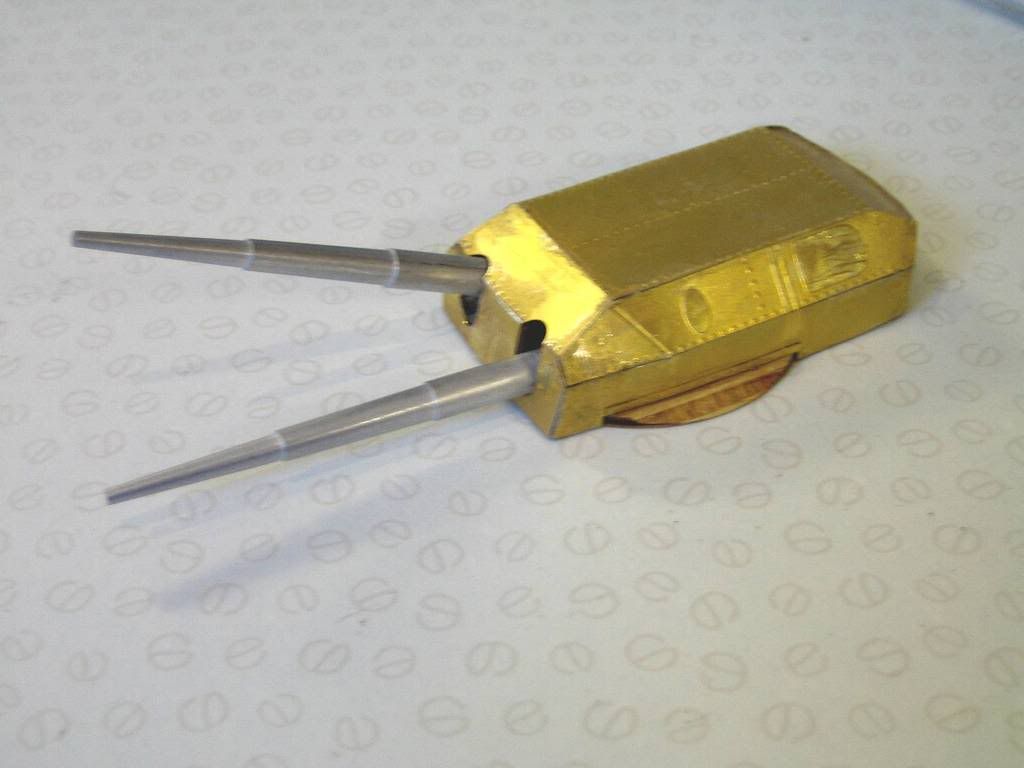
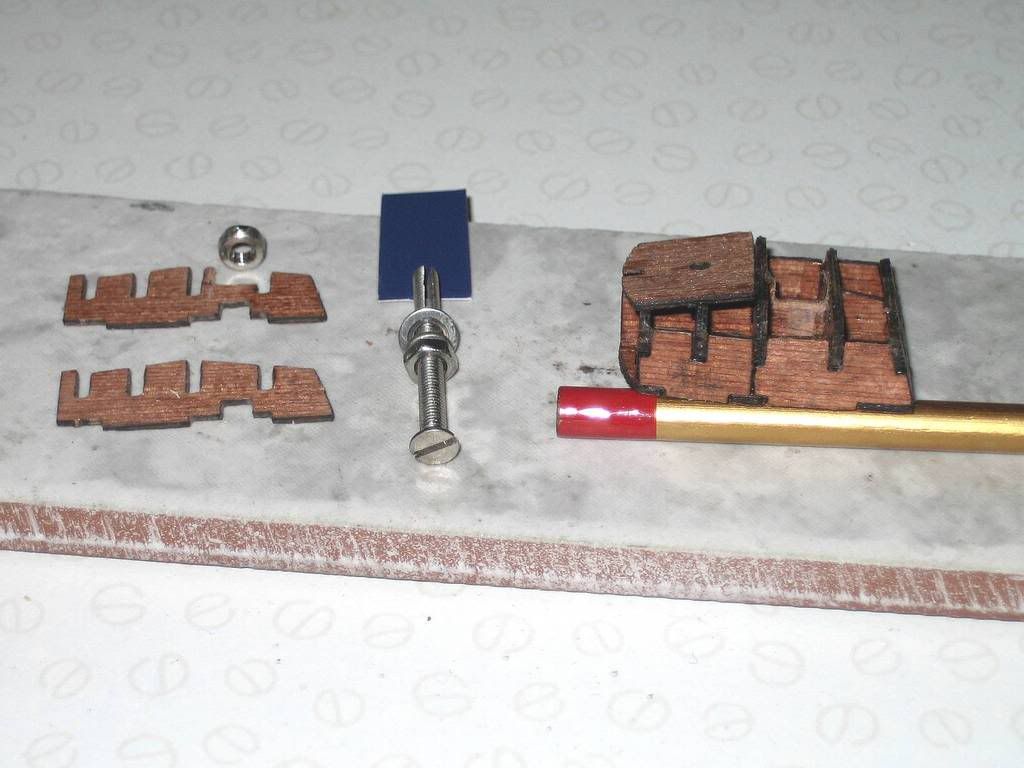
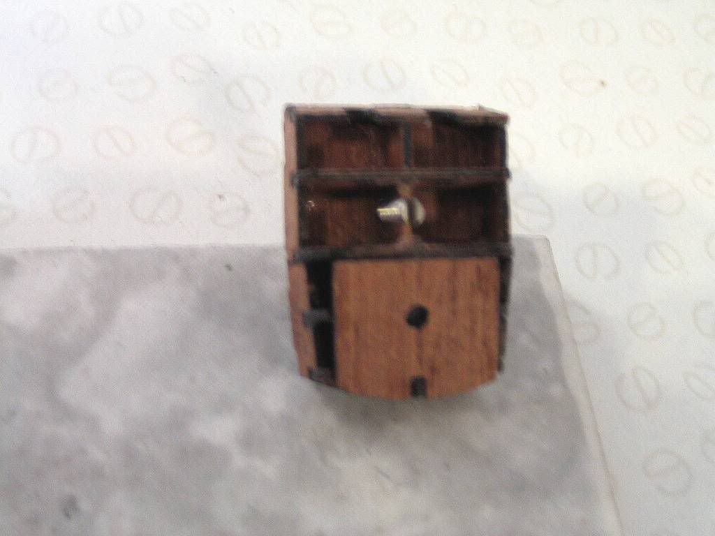
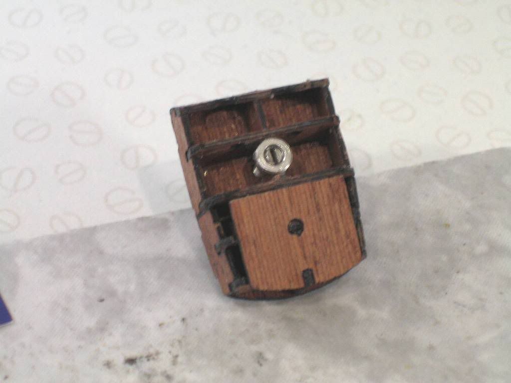
I have now designed the main turrets and their gun barrels and servos. The pictures and details of the construction are posted on my Flickr site in the set called "Bismarck Main (380 mm) Gun Turret" at: www.flickr.com/photos/commander-popeye/The following photos are a selection to see how the main fitting was done. By using a screw extension to the servo, it mean that I do not have to cut a large hole underneath the turret to accomodate a servo directly underneath. The servos are driven from the RC receiver via a servo slowing device (it costs about £12 and will drive 2 separate servos from 2 receiver signals) that increases the time of the servo movement to about 3 seconds for a 180 degree turn. More than one servo can be driven from each output of the slowmo. The gun barrels come from www.euromodels.co.uk, they are 1:200 scale 380mm main ship gun barrels. They are 80mm long, a perfect fit, and cost about £1.30p each. 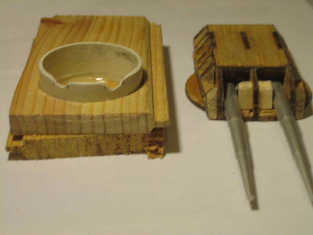 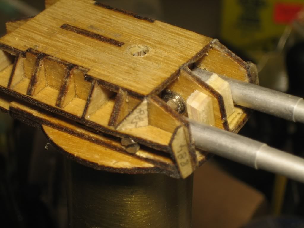 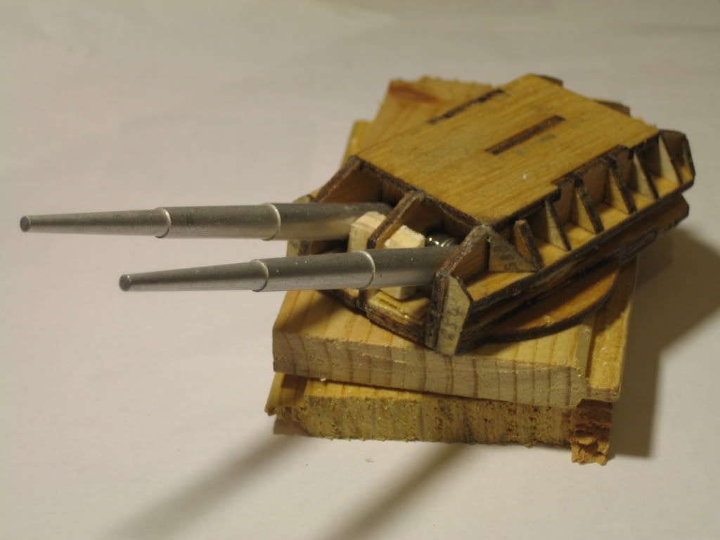 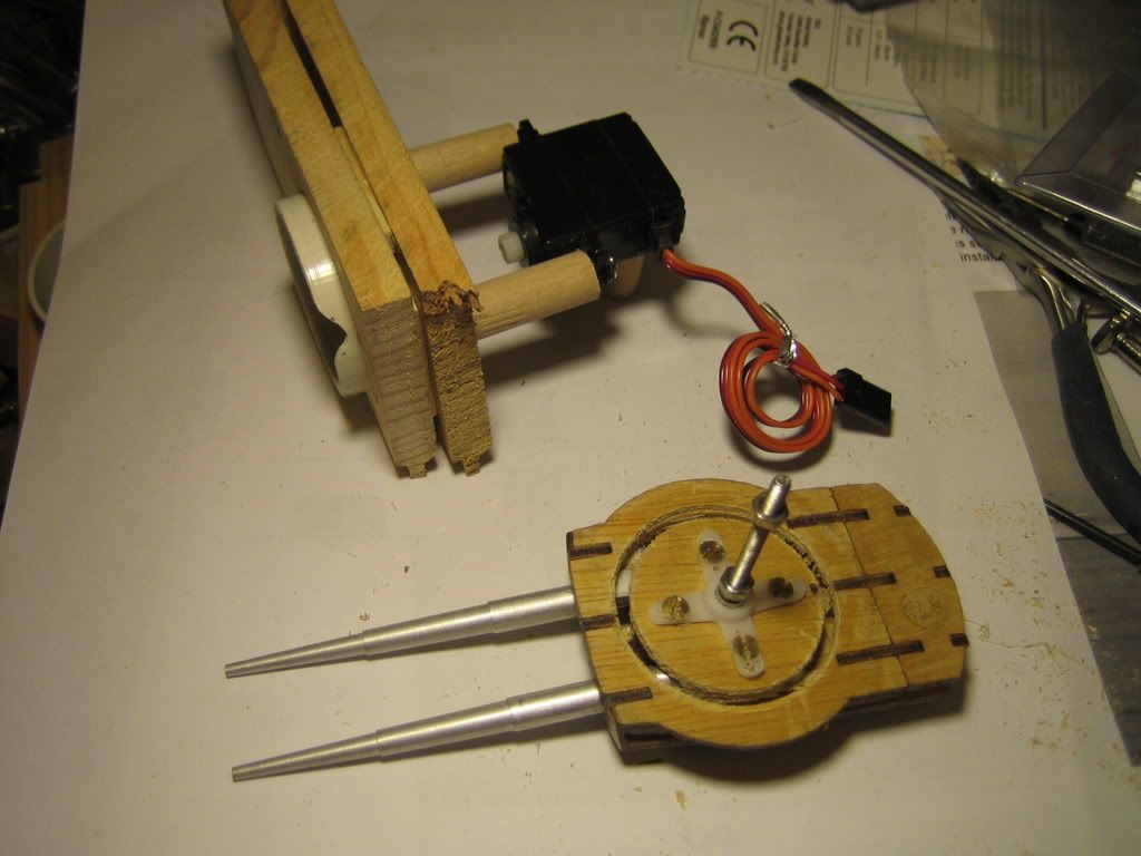 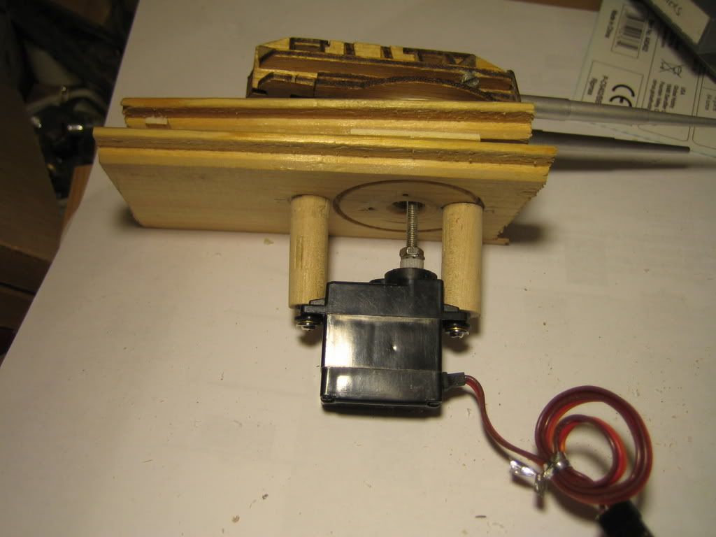 |
|
|
|
Post by popeye on Jan 2, 2009 14:18:24 GMT 1
The servo that I got for the main turret control was one of a number of "mini" servos that my local model shop sold. It is a Cirrus CS402/BB Mini Servo - 18 gram/0.64 oz. It measures 28x13x33 mm and turns through 180 degress in about 0.2 seconds (without the slowing device). it delivers about 2kg/cm 30oz/in torque. The internal mechanical stops actually allow it to rotate 270 degrees so with a modern radio control transmitter that allows you to "overdrive" a servo by up to 50%, you can get more than 180 degrees of turn. Hope this helps. This is a picture of the servo slowing device  This device takes 2 inputs from the radio control receiver and has 2 separate outputs (one from each input, which can drive more than one servo on each output, e.g. by using a "Y" cable) which drive a servo slowly. The speed adjustment is via a small variable resistor on the board (the screwdriver is pointing to the adjuster). It can slow a servo down to about 3 seconds to turn by 180 degrees |
|
|
|
Post by david on Jan 3, 2009 22:17:01 GMT 1
Impressive work Popeye, I can't make up my mind whether or not to motorise the turrets, I'm so behind with the rest of my build. But keep posting the pictures!
|
|
|
|
Post by popeye on Feb 10, 2009 0:48:27 GMT 1
|
|
|
|
Post by popeye on Feb 11, 2009 15:32:32 GMT 1
Looking forward to seeing anybody who comes to the Brighton ModelWorld (this Fri-Sun 13-15 Feb). I am on the model boat stand by the pond and running my live steam plant for my 9ft Yamato battleship. I will also have my Bismarck there. I'm the one with the large beard and moustache, bald on top and amply constructed !
|
|
|
|
Post by eric on Feb 11, 2009 17:06:55 GMT 1
Excellent work on your turrets Popeye, I wish I was brave enough to power my turrets, but to me it's all a bit too complex!
I'm content to have the ship with powered props and rudders only, my poor brain can just about cope with that!
|
|
|
|
Post by david on Feb 11, 2009 22:59:33 GMT 1
I'm with you there Eric, I'm lost in admiration of Popeye and all the forum members who've gone motorised. This modelling virgin is sticking with traditional digital turrets ie. forefinger control! Good to see the progress on your model Eric; at the rate I'm going, I expect to be the last man modelling.
|
|
Deleted
Deleted Member
Posts: 0
|
Post by Deleted on Feb 12, 2009 5:51:28 GMT 1
Maybe David, the way I'm going I could well be the last!!!!!
That is, if I ever finish the Bismarck!!!
|
|
|
|
Post by Achtung!! on Feb 12, 2009 8:47:51 GMT 1
I'm with you there Eric, I'm lost in admiration of Popeye and all the forum members who've gone motorised. This modelling virgin is sticking with traditional digital turrets ie. forefinger control! Good to see the progress on your model Eric; at the rate I'm going, I expect to be the last man modelling. Dont think you'll be alone somehow... |
|